В этом примере показана адаптация MySensors с esp8266 WiFi и mqtt шлюзом при работе с Sonoff реле. Я также включил небольшой пример конфигурации Home Assistant для Ethernet и mqtt.
Тестирование при 220В, но это ваша ответственность.
При запуске светодиод мигнет два раза после того, как презентация будет сделана, а затем запуститься в выключенном состоянии. При включении/выключении посылает состояние к шлюзу, шлюз посылает состояние к Sonoff.
Оба скетча зависят от Bounce2 (2.2.0) в Arduino IDE диспетчере библиотек (не MySensors библиотека примеров)
Sonoff некоторые детали (IM15116002)
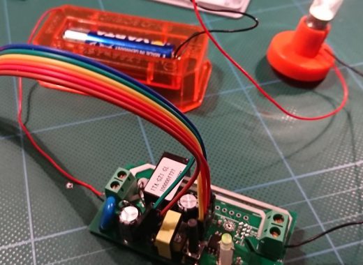
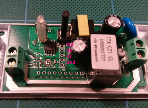
The sonoff header left to right, relay above, LED below.
 *  [1]  vcc 3v3
 *   2   rx
 *   3   tx
 *   4   gnd
 *   5
В arduinoIDE старше 1.6.* выбрать Generic ESP8226 модуль. Удерживайте кнопку Sonoff при подключении ftdi к флэш.
Ethernet:
/**
 * The MySensors Arduino library handles the wireless radio link and protocol
 * between your home built sensors/actuators and HA controller of choice.
 * The sensors forms a self healing radio network with optional repeaters. Each
 * repeater and gateway builds a routing tables in EEPROM which keeps track of the
 * network topology allowing messages to be routed to nodes.
 *
 * Created by Henrik Ekblad <henrik.ekblad@mysensors.org>
 * Copyright (C) 2013-2015 Sensnology AB
 * Full contributor list: https://github.com/mysensors/Arduino/graphs/contributors
 *
 * Documentation: http://www.mysensors.org
 * Support Forum: http://forum.mysensors.org
 *
 * This program is free software; you can redistribute it and/or
 * modify it under the terms of the GNU General Public License
 * version 2 as published by the Free Software Foundation.
 *
 *******************************
 *
 * REVISION HISTORY
 * Version 1.0 - Henrik EKblad
 * Contribution by a-lurker and Anticimex,
 * Contribution by Norbert Truchsess <norbert.truchsess@t-online.de>
 * Contribution by Ivo Pullens (ESP8266 support)
 *
 * DESCRIPTION
 * The EthernetGateway sends data received from sensors to the WiFi link.
 * The gateway also accepts input on ethernet interface, which is then sent out to the radio network.
 *
 * VERA CONFIGURATION:
 * Enter "ip-number:port" in the ip-field of the Arduino GW device. This will temporarily override any serial configuration for the Vera plugin.
 * E.g. If you want to use the defualt values in this sketch enter: 192.168.178.66:5003
 *
 * LED purposes:
 * - To use the feature, uncomment any of the MY_DEFAULT_xx_LED_PINs in your sketch, only the LEDs that is defined is used.
 * - RX (green) - blink fast on radio message recieved. In inclusion mode will blink fast only on presentation recieved
 * - TX (yellow) - blink fast on radio message transmitted. In inclusion mode will blink slowly
 * - ERR (red) - fast blink on error during transmission error or recieve crc error
 *
 * See http://www.mysensors.org/build/esp8266_gateway for wiring instructions.
 * nRF24L01+  ESP8266
 * VCC        VCC
 * CE         GPIO4
 * CSN/CS     GPIO15
 * SCK        GPIO14
 * MISO       GPIO12
 * MOSI       GPIO13
 * GND        GND
 *
 * Not all ESP8266 modules have all pins available on their external interface.
 * This code has been tested on an ESP-12 module.
 * The ESP8266 requires a certain pin configuration to download code, and another one to run code:
 * - Connect REST (reset) via 10K pullup resistor to VCC, and via switch to GND ('reset switch')
 * - Connect GPIO15 via 10K pulldown resistor to GND
 * - Connect CH_PD via 10K resistor to VCC
 * - Connect GPIO2 via 10K resistor to VCC
 * - Connect GPIO0 via 10K resistor to VCC, and via switch to GND ('bootload switch')
 *
  * Inclusion mode button:
 * - Connect GPIO5 via switch to GND ('inclusion switch')
 *
 * Hardware SHA204 signing is currently not supported!
 *
 * Make sure to fill in your ssid and WiFi password below for ssid & pass.
 */

/**
 * Sonoff specific details (IM15116002)
 *
 * The sonoff header left to right, relay above, LED below.
 *  [1]  vcc 3v3
 *   2   rx
 *   3   tx
 *   4   gnd
 *   5
 *
 * In arduinoIDE 1.6.* choose Generic ESP8226 module.
 * Hold Sonoff button when attaching FTDI to flash.
 */

// Enable debug prints to serial monitor
#define MY_DEBUG

// Use a bit lower baudrate for serial prints on ESP8266 than default in MyConfig.h
#define MY_BAUD_RATE 9600

// No radio in Sonoff
// Enables and select radio type (if attached)
// #define MY_RADIO_NRF24
// #define MY_RADIO_RFM69

#define MY_GATEWAY_ESP8266

#define MY_ESP8266_SSID "MySSID"
#define MY_ESP8266_PASSWORD "MyVerySecretPassword"

// Enable UDP communication
//#define MY_USE_UDP

// Set the hostname for the WiFi Client. This is the hostname
// it will pass to the DHCP server if not static.
// #define MY_ESP8266_HOSTNAME "sensor-gateway"

// Enable MY_IP_ADDRESS here if you want a static ip address (no DHCP)
#define MY_IP_ADDRESS 192,168,178,87

// If using static ip you need to define Gateway and Subnet address as well
#define MY_IP_GATEWAY_ADDRESS 192,168,178,1
#define MY_IP_SUBNET_ADDRESS 255,255,255,0

// The port to keep open on node server mode
#define MY_PORT 5003

// How many clients should be able to connect to this gateway (default 1)
#define MY_GATEWAY_MAX_CLIENTS 1

// Controller ip address. Enables client mode (default is "server" mode).
// Also enable this if MY_USE_UDP is used and you want sensor data sent somewhere.
// #define MY_CONTROLLER_IP_ADDRESS 192, 168, 178, 68

/*
// Enable inclusion mode
#define MY_INCLUSION_MODE_FEATURE

// Enable Inclusion mode button on gateway
// #define MY_INCLUSION_BUTTON_FEATURE
// Set inclusion mode duration (in seconds)
#define MY_INCLUSION_MODE_DURATION 60
// Digital pin used for inclusion mode button
#define MY_INCLUSION_MODE_BUTTON_PIN  3


// Set blinking period
// #define MY_DEFAULT_LED_BLINK_PERIOD 300

// Flash leds on rx/tx/err
// Led pins used if blinking feature is enabled above
#define MY_DEFAULT_ERR_LED_PIN 16  // Error led pin
#define MY_DEFAULT_RX_LED_PIN  16  // Receive led pin
#define MY_DEFAULT_TX_LED_PIN  16  // the PCB, on board LED
*/

#if defined(MY_USE_UDP)
#include <WiFiUdp.h>
#endif

#include <ESP8266WiFi.h>
#include <MySensors.h>
#include <Bounce2.h>

#define BUTTON_PIN 0  // Sonoff pin number for button
#define RELAY_PIN 12  // Sonoff pin number for relay
#define LED_PIN 13    // Sonoff pin number for LED
#define RELAY_ON 1
#define RELAY_OFF 0
#define LED_ON 0
#define LED_OFF 1

// Id of the sensor child
// Set unique id for each sonoff if sub/pub on same mqtt topic
#define CHILD_ID 0

Bounce debouncer = Bounce();
int oldValue = 0;
bool state = false;

MyMessage msg(CHILD_ID,V_STATUS);

void setup()
{
  // Setup the button
  pinMode(BUTTON_PIN, INPUT_PULLUP);

  // After setting up the button, setup debouncer
  debouncer.attach(BUTTON_PIN);
  debouncer.interval(5);

  // Make sure relays and LED are off when starting up
  digitalWrite(RELAY_PIN, RELAY_OFF);
  digitalWrite(LED_PIN, LED_OFF);

  // Then set relay pins in output mode
  pinMode(RELAY_PIN, OUTPUT);
  pinMode(LED_PIN, OUTPUT);
}

void presentation()  {
  // Send the sketch version information
  sendSketchInfo("Sonoff ethernet", "1.0");
  // Register sensor
  present(CHILD_ID, S_BINARY);
  // Send the current state
  send(msg.set(state?true:false));
  // Blink when ready
  blink();
}


void loop()
{
  debouncer.update();
  // Get the update value
  int value = debouncer.read();
  if (value != oldValue && value==0) {
    // Toggle the state
    state = state?false:true;
    // Change relay state
    digitalWrite(RELAY_PIN, state?RELAY_ON:RELAY_OFF);
    // Change LED state
    digitalWrite(LED_PIN, state?LED_ON:LED_OFF);
    // Send new state
    send(msg.set(state));
  }
  oldValue = value;
}

void receive(const MyMessage &message)
{
  // We only react on status messages from the controller
  // to this CHILD_ID.
  if (message.type==V_STATUS  && message.sensor==CHILD_ID) {
    // Change relay state
    // Only switch if the state is new
    if (message.getBool() != state) {
      state = message.getBool();
      // Change relay state
      digitalWrite(RELAY_PIN, state?RELAY_ON:RELAY_OFF);
      // Change LED state
      digitalWrite(LED_PIN, state?LED_ON:LED_OFF);
       // Send the current state
      send(msg.set(state));
    }
  }
}

void blink()
{
  digitalWrite(LED_PIN, digitalRead(LED_PIN)?LED_ON:LED_OFF);
  wait(200);
  digitalWrite(LED_PIN, digitalRead(LED_PIN)?LED_ON:LED_OFF);
  wait(200);
  digitalWrite(LED_PIN, digitalRead(LED_PIN)?LED_ON:LED_OFF);
  wait(200);
  digitalWrite(LED_PIN, digitalRead(LED_PIN)?LED_ON:LED_OFF);
}
MQTT
Если у вас есть несколько Sonoff, все они могут использовать один и тот же mqtt topic , пока они не имеют тот же child ID.
/**
 * The MySensors Arduino library handles the wireless radio link and protocol
 * between your home built sensors/actuators and HA controller of choice.
 * The sensors forms a self healing radio network with optional repeaters. Each
 * repeater and gateway builds a routing tables in EEPROM which keeps track of the
 * network topology allowing messages to be routed to nodes.
 *
 * Created by Henrik Ekblad <henrik.ekblad@mysensors.org>
 * Copyright (C) 2013-2015 Sensnology AB
 * Full contributor list: https://github.com/mysensors/Arduino/graphs/contributors
 *
 * Documentation: http://www.mysensors.org
 * Support Forum: http://forum.mysensors.org
 *
 * This program is free software; you can redistribute it and/or
 * modify it under the terms of the GNU General Public License
 * version 2 as published by the Free Software Foundation.
 *
 *******************************
 *
 * REVISION HISTORY
 * Version 1.0 - Henrik Ekblad
 *
 * DESCRIPTION
 * The ESP8266 MQTT gateway sends radio network (or locally attached sensors) data to your MQTT broker.
 * The node also listens to MY_MQTT_TOPIC_PREFIX and sends out those messages to the radio network
 *
 * LED purposes:
 * - To use the feature, uncomment any of the MY_DEFAULT_xx_LED_PINs in your sketch
 * - RX (green) - blink fast on radio message recieved. In inclusion mode will blink fast only on presentation recieved
 * - TX (yellow) - blink fast on radio message transmitted. In inclusion mode will blink slowly
 * - ERR (red) - fast blink on error during transmission error or recieve crc error
 *
 * See http://www.mysensors.org/build/esp8266_gateway for wiring instructions.
 * nRF24L01+  ESP8266
 * VCC        VCC
 * CE         GPIO4
 * CSN/CS     GPIO15
 * SCK        GPIO14
 * MISO       GPIO12
 * MOSI       GPIO13
 *
 * Not all ESP8266 modules have all pins available on their external interface.
 * This code has been tested on an ESP-12 module.
 * The ESP8266 requires a certain pin configuration to download code, and another one to run code:
 * - Connect REST (reset) via 10K pullup resistor to VCC, and via switch to GND ('reset switch')
 * - Connect GPIO15 via 10K pulldown resistor to GND
 * - Connect CH_PD via 10K resistor to VCC
 * - Connect GPIO2 via 10K resistor to VCC
 * - Connect GPIO0 via 10K resistor to VCC, and via switch to GND ('bootload switch')
 *
  * Inclusion mode button:
 * - Connect GPIO5 via switch to GND ('inclusion switch')
 *
 * Hardware SHA204 signing is currently not supported!
 *
 * Make sure to fill in your ssid and WiFi password below for ssid & pass.
 */

/**
 * Sonoff specific details (IM15116002)
 *
 * The sonoff header left to right, relay above, LED below.
 *  [1]  vcc 3v3
 *   2   rx
 *   3   tx
 *   4   gnd
 *   5
 *
 * In arduinoIDE 1.6.* choose Generic ESP8226 module.
 * Hold Sonoff button when attaching FTDI to flash.
 */


// Enable debug prints to serial monitor
#define MY_DEBUG

// Use a bit lower baudrate for serial prints on ESP8266 than default in MyConfig.h
#define MY_BAUD_RATE 9600

// No radio in Sonoff
// Enables and select radio type (if attached)
//#define MY_RADIO_NRF24
//#define MY_RADIO_RFM69

#define MY_GATEWAY_MQTT_CLIENT
#define MY_GATEWAY_ESP8266

// Set this node's subscribe and publish topic prefix
#define MY_MQTT_PUBLISH_TOPIC_PREFIX "sonoff-out"
#define MY_MQTT_SUBSCRIBE_TOPIC_PREFIX "sonoff-in"

// Set MQTT client id
#define MY_MQTT_CLIENT_ID "mysensors-sonoff-1"

// Enable these if your MQTT broker requires usenrame/password
//#define MY_MQTT_USER "username"
//#define MY_MQTT_PASSWORD "password"

// Set WIFI SSID and password
#define MY_ESP8266_SSID "SSiD"
#define MY_ESP8266_PASSWORD "password"

// Set the hostname for the WiFi Client. This is the hostname
// it will pass to the DHCP server if not static.
#define MY_ESP8266_HOSTNAME "mqtt-sensor-gateway-sonoff-1"

// Enable MY_IP_ADDRESS here if you want a static ip address (no DHCP)
//#define MY_IP_ADDRESS 192,168,178,87

// If using static ip you need to define Gateway and Subnet address as well
#define MY_IP_GATEWAY_ADDRESS 192,168,0,1
#define MY_IP_SUBNET_ADDRESS 255,255,255,0


// MQTT broker ip address.
#define MY_CONTROLLER_IP_ADDRESS 192, 168, 0, 100

// The MQTT broker port to to open
#define MY_PORT 1883

// Not tested for Sonoff
/*
// Enable inclusion mode
#define MY_INCLUSION_MODE_FEATURE
// Enable Inclusion mode button on gateway
#define MY_INCLUSION_BUTTON_FEATURE
// Set inclusion mode duration (in seconds)
#define MY_INCLUSION_MODE_DURATION 60
// Digital pin used for inclusion mode button
#define MY_INCLUSION_MODE_BUTTON_PIN  3

// Set blinking period
#define MY_DEFAULT_LED_BLINK_PERIOD 300

// Flash leds on rx/tx/err
#define MY_DEFAULT_ERR_LED_PIN 16  // Error led pin
#define MY_DEFAULT_RX_LED_PIN  16  // Receive led pin
#define MY_DEFAULT_TX_LED_PIN  16  // the PCB, on board LED
*/

#include <ESP8266WiFi.h>
#include <MySensors.h>
#include <Bounce2.h>

#define BUTTON_PIN 0  // Sonoff pin number for button
#define RELAY_PIN 12  // Sonoff pin number for relay
#define LED_PIN 13    // Sonoff pin number for LED
#define RELAY_ON 1
#define RELAY_OFF 0
#define LED_ON 0
#define LED_OFF 1

// Id of the sensor child
// Set unique id for each sonoff if sub/pub on same mqtt topic
#define CHILD_ID 0

Bounce debouncer = Bounce();
int oldValue = 0;
bool state = false;

MyMessage msg(CHILD_ID,V_STATUS);

void setup()
{
  // Setup the button
  pinMode(BUTTON_PIN, INPUT_PULLUP);

  // After setting up the button, setup debouncer
  debouncer.attach(BUTTON_PIN);
  debouncer.interval(5);

  // Make sure relays and LED are off when starting up
  digitalWrite(RELAY_PIN, RELAY_OFF);
  digitalWrite(LED_PIN, LED_OFF);

  // Then set relay pins in output mode
  pinMode(RELAY_PIN, OUTPUT);
  pinMode(LED_PIN, OUTPUT);
}

void presentation()  {
  // Send the sketch version information
  sendSketchInfo("Sonoff", "1.0");
  // Register sensor
  present(CHILD_ID, S_BINARY);
  // Send the current state
  send(msg.set(state?true:false));
  // Blink when ready
  blink();
}


void loop()
{
  debouncer.update();
  // Get the update value
  int value = debouncer.read();
  if (value != oldValue && value==0) {
    // Toggle the state
    state = state?false:true;
    // Change relay state
    digitalWrite(RELAY_PIN, state?RELAY_ON:RELAY_OFF);
    // Change LED state
    digitalWrite(LED_PIN, state?LED_ON:LED_OFF);
    // Send new state
    send(msg.set(state));
  }
  oldValue = value;
}

void receive(const MyMessage &message)
{
  // We only react on status messages from the controller
  // to this CHILD_ID.
  if (message.type==V_STATUS  && message.sensor==CHILD_ID) {
    // Change relay state
    // Only switch if the state is new
    if (message.getBool() != state) {
      state = message.getBool();
      // Change relay state
      digitalWrite(RELAY_PIN, state?RELAY_ON:RELAY_OFF);
      // Change LED state
      digitalWrite(LED_PIN, state?LED_ON:LED_OFF);
       // Send the current state
      send(msg.set(state));
    }
  }
}

void blink()
{
  digitalWrite(LED_PIN, digitalRead(LED_PIN)?LED_ON:LED_OFF);
  wait(200);
  digitalWrite(LED_PIN, digitalRead(LED_PIN)?LED_ON:LED_OFF);
  wait(200);
  digitalWrite(LED_PIN, digitalRead(LED_PIN)?LED_ON:LED_OFF);
  wait(200);
  digitalWrite(LED_PIN, digitalRead(LED_PIN)?LED_ON:LED_OFF);
}
HASS настройка не большая. Используя persistence file можно с помощью HASS восстановить необходимое состояние Sonoff после отключения питания.
mysensors:
  gateways:
    # For ethernet
    - device: '192.168.178.87'
      persistence_file: '/home/homeassistant/.homeassistant/sonoff-ethernet1.json'
      tcp_port: 5003
   # For mqtt
   - device: mqtt
      persistence_file: '/home/homeassistant/.homeassistant/sonoff.json'
      topic_in_prefix: 'sonoff-out'
      topic_out_prefix: 'sonoff-in'
  debug: false
  optimistic: false
  persistence: true
  retain: true
  version: 2.0
Изображения
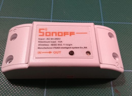
Спецификация
| Кол-во | Цена | MF | MPN | Ссылки на Aliexpress или Ebay |
|---|---|---|---|---|
| 1 | $6 | ITEAD | IM15116002 | ITead: https://www.itead.cc/sonoff-wifi-wireless-switch.html |
Перевёл Антон Вотчицев
